The channel strip
The tile in the bay
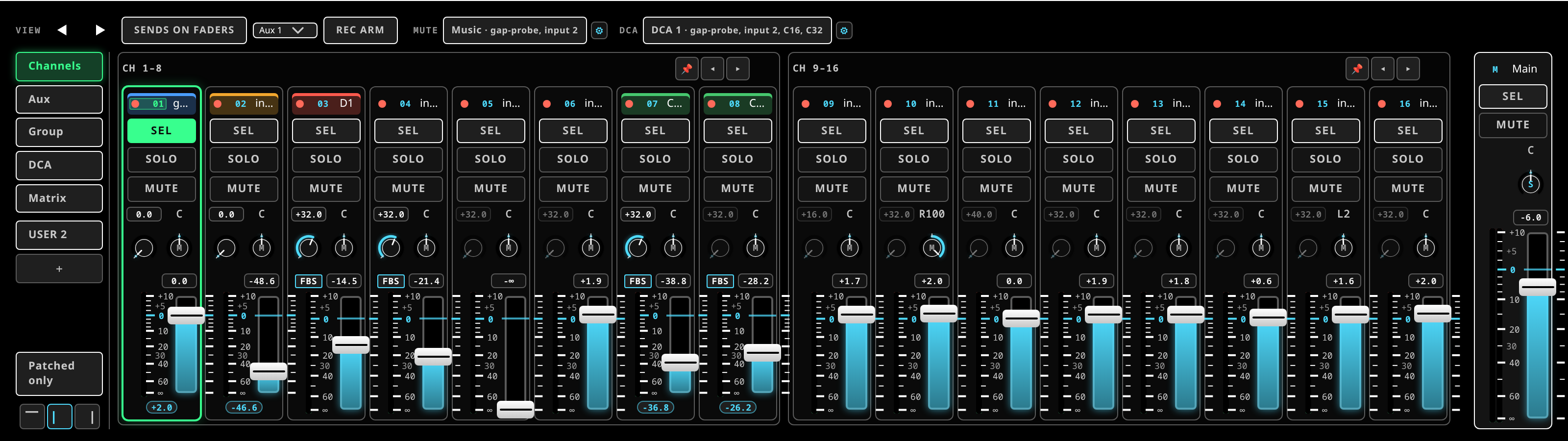 The fader bay: tiles in banks of eight, the selected strip outlined, MAIN pinned to the right.
Each strip in the fader bay shows, top to bottom:
- a small state dot — grey when silent, green on signal, red on clip, and a distinct
colour when the engine has flagged a feedback ring on the channel — and the strip
number (
Mfor Main); - the name, which you click to rename, and a scribble colour;
- a latency badge that opens the channel's latency breakdown, and turns hot when the path runs long;
- the head-amp gain control — the input trim, a different control from the fader;
- the meter (one column for mono, an L/R pair for a linked or stereo strip, each with peak-hold);
- the fader with its dB readout;
- mute and solo (Main has no solo);
- one-tap live helpers: a −6 trim, TAME for a ringing channel, and SPARE to swap in a spare.
Pan and the deeper processing are deliberately not on the tile. You reach them by selecting the strip and opening the channel view above, which keeps the tile itself large and thumb-friendly.
Badges on the tile
A tile carries a badge only while there is something to say, so a tile with none is a clean channel rather than an unfinished one.
- FBS and HRP — the feedback suppressor or the harmonic processor is on for this channel. A plain badge means armed and listening; lit solid with a glow, it is cutting right now.
- HELD (red) — a mute group or PANIC is silencing the channel, whatever its own MUTE says. Release it where it was set: the mute group, or PANIC.
- SIP (amber) — a solo-in-place is keeping the channel out of MAIN. Clear the solo, or make the channel solo-safe.
- FEED (red, glowing) — on a mix: the output leg this mix feeds is muted, so the destination it names is silent while the mix itself still meters.
- NO DEVICE (red) — the channel is patched to hardware that is not on the rig, so it passes no audio. Hover it for the device it is waiting on.
- TRK — the channel is playing a recorded track in a virtual soundcheck instead of its live input.
- a dB figure in an outlined chip — a DCA is pulling on this channel, and the figure is the level it actually plays at with every DCA over it applied.
- the latency badge — the path's total in milliseconds, amber above 12 ms. Press it for the breakdown.
Mixing a channel
Signal order
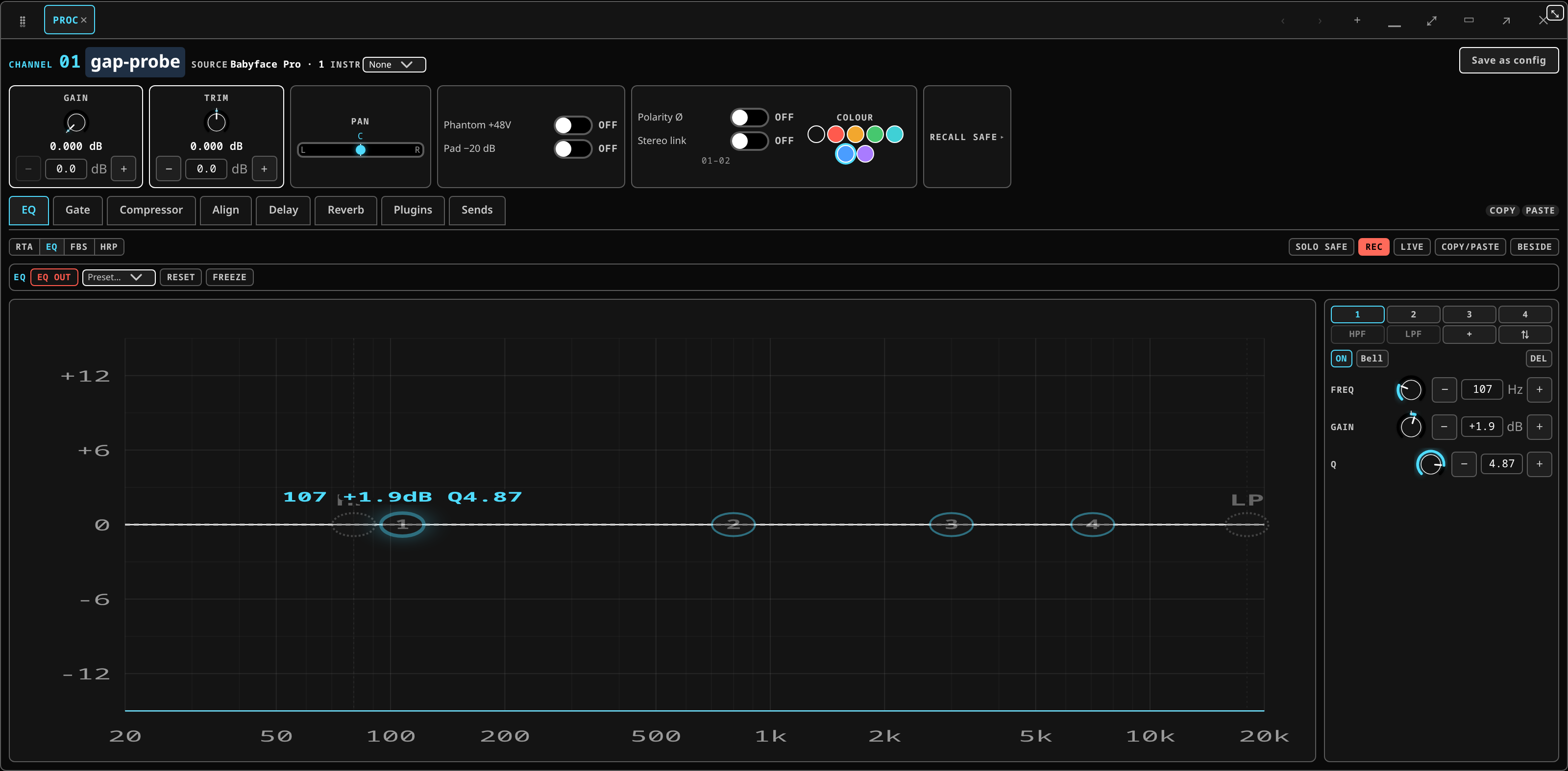 The channel view for the selected strip: the head-amp row on top, then the section tabs.
Select a channel and open the Processing chip. The strip lays the signal out in order:
head amp → trim → high-pass / low-pass → gate → EQ → dynamics → inserts → fader → sends → bus
with a chip for each of the parts you edit most: EQ, Gate, Compressor, Speakers, Delay, Reverb, Plugins and Sends. Which of them appear depends on the strip: a bus has no corrector and no alignment, and a console profile modelled on a desk with no delay strip does not show one. The spectrum analyser (RTA) is always visible beside the controls, whichever chip you have open. See EQ and dynamics and alignment.
Analysis is a stacked chip rather than a single door: alignment, the feedback suppressor and the harmonic resonance processor each get a row on it, showing their name, where they stand, and their own on/off switch. Click a row's name to bring that one's controls up; throw its switch to arm or release it without leaving what you are looking at.
Every stage switches in and out with the same switch — the EQ, the gate, the compressor, the analyser and the two correctors all read the same way, on the chip and in the controls beside it.
Each stage's controls window carries copy and paste in its top corner: copy takes that one stage from this channel, and paste puts it on another. Paste stays dim until the clipboard holds that stage and the channel you are on can carry it; hovering says which of the two is missing. The whole channel's copy/paste is still in the channel bar's ⋯ menu.
The order of the processing blocks is not fixed — the default console profile allows free reordering, and the plugin rack is where you move inserts within the chain.
Badges on the channel view's header
The channel view's header line repeats the facts that change what you are hearing:
- STEREO — the strip is a linked or stereo pair, and its controls move both legs.
- NO DEVICE (red) — the source this channel is patched from is not on the rig. Hover it for the reason.
- NOT LANDED (amber) — a head-amp setting, phantom power or the pad, was sent to the box and the box has not confirmed it. One badge covers the whole head amp; hover it for which setting and why. See trusting what you see.
Gain staging
Set gain at the head amp first, so the channel meter sits in its working range and never touches clip on the loudest part of the material. Then shape with EQ, gate and compressor, add any plugin inserts, and ride the fader.
The fader is for balance. If you are using it to find signal, the gain is wrong.
Two distinct controls are easy to confuse:
- Head-amp gain / sensitivity — the analogue input stage, before conversion. On a stagebox channel this control is the box's sensitivity; see head-amp control.
- Trim — a fine digital adjustment after conversion, composing with the gain.
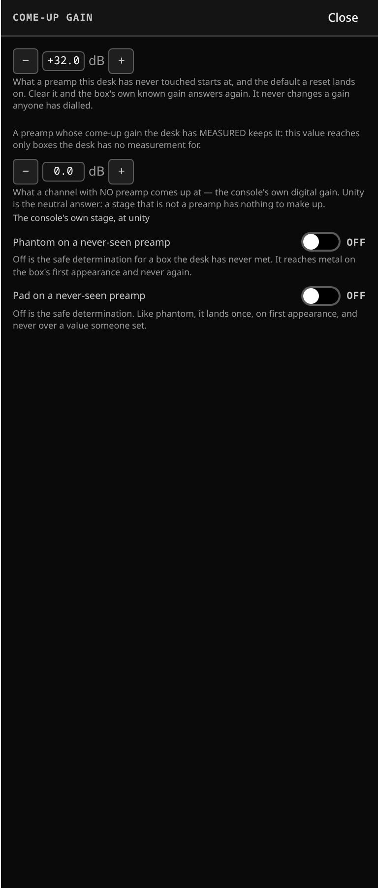 Come-up gain, in the config zone: the make-up the desk applies when a source is brought up.
Pan
A channel's pan control places it in the stereo image, dead centre at rest. It is one dial — there is no separate balance control on a channel strip; MAIN's own pan is its balance (see buses are strips too).
What this stage guarantees: Every sample this stage produces is a finite number — never NaN, never infinite. Panning follows a constant-power law: centre sits 3 dB down on each side so the perceived loudness stays constant.
The channel overview
The Channel overview panel shows the whole of the selected channel on one screen: every stage as a small card, each with its own encoders, so you can read a channel at a glance instead of stepping through the tabs. Add it from LAYOUTS ▸ Add panel like any other panel.
The cards read top to bottom in the channel's own order:
- Input — gain, pad, 48 V and polarity. On a strip with no head amp (a bus, or a channel with nothing patched to a preamp) the whole card is greyed and says why; it is never hidden, so you can always see that the channel has no input stage rather than wondering where it went.
- one card per processing stage — Gate, EQ, Compressor, Drive, Delay and Reverb — in the order this channel actually runs them. If you drag the processing tabs into a different order, the cards follow, because both read the same channel setting. Each card has the section's on/off switch beside its name.
- Fader — the fader, pan, mute and the channel's meter.
- Sends — one bar per destination.
Gate, EQ, Compressor and Drive draw a small picture of what they are doing — the gate and compressor curves, the EQ response, the drive's shape. Delay and Reverb carry encoders only. The pictures are there to be read, not grabbed: to edit a curve by hand, open the section.
Every encoder is the real control. Turn one and the channel changes, exactly as it would on the section's own tab; double-click resets it to the value the desk itself comes up at. Each encoder is drawn from the travel this channel reports — a preamp that reaches 65 dB shows 65 — and a control the desk has not described yet is shown greyed rather than over an invented scale.
The card's title is a door. Click the name on any card and the Processing panel opens on that section, on the same channel.
The send bars
Each bar is one destination: its short name, how far the send is up, the dB, and a PRE tag
when the send is pre-fader. Tap a bar and the fader bay flips to sends-on-faders for that
destination, which is where a send is actually ridden — see
sends, buses and DCAs.
The bars show the send LEVEL, not audio. They move when a send moves; they do not meter what is going down it.
The bay overview
The Bay overview panel is the same cards for eight strips side by side, one column each, with the rows lined up across the bay: every gate on one line, every EQ on the next. It is how you compare a bank — see at a glance which channels have a gate in, where the drive is up, which one has a send open.
- It follows the fader bay. The eight strips are the bank the bay is showing; page the wall and the overview pages with it. There is no separate navigator.
- The selected channel's column is lit, and clicking a column head selects that channel — the same selection every other screen uses.
- Each column draws its own channel's order, so a channel whose stages were reordered reads as an odd column. That is deliberate: the bay shows you what each channel really does.
- A bank with fewer than eight strips draws the columns it has.
- Every encoder works exactly as it does in the channel overview, on that column's channel.
Narrow the panel and the columns get tighter, down to a floor: past it the panel scrolls sideways rather than dropping a strip or wrapping a column onto a second row. Eight stay eight.
Mute and solo
Mute and solo are on the tile and echo to every screen. Solo feeds the cue and monitor path, not the mains — see cue, solo and the monitor for what PFL, AFL and solo-in-place each do, and for the momentary solo-clear.
A channel muted by a mute group keeps its own mute state underneath: release the group and it returns exactly as it was.
Stereo channels and linking
Two different things, both available from the strip:
- Link folds two adjacent mono channels into an odd–even pair —
03–04— so they move together. Console muscle memory: either channel of the pair names the pair. - Width makes the selected channel a single strip carrying an intrinsic L/R pair.
A linked or stereo strip meters as an L/R pair. Beside its name every strip carries a small width tag: S, lit, on a stereo strip, and M on a mono one.
Renaming and colour
Click the name on the tile to rename it. The scribble colour is identity metadata only — it changes nothing about the signal, and it is what makes a wall of 48 channels readable from the back of a room.
Buses are strips too
An aux or a group master reuses the same processing view: a bus has its own chain, its own EQ and dynamics, and its own inserts. What it does not have is a head amp, and the sections that make no sense on a bus are simply absent rather than greyed out.