The matrix and outputs
The crosspoint matrix
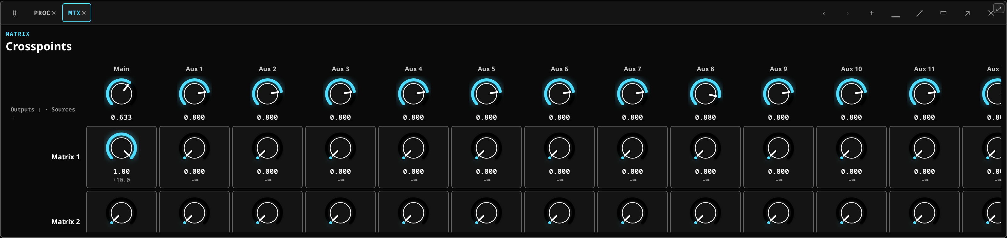 The crosspoint matrix: a cell per source and destination, each carrying its own level.
The Matrix + outputs chip holds the matrix: a grid whose rows are matrix outputs and whose columns are the buses and mains that can feed them. Each crosspoint is a level control with a dB readout, and each source column carries its own master.
A matrix output is any blend of the mains and the buses, at levels you set. That is how you build:
- a delay-tower or fill feed — the mains, at a level and with a delay of its own;
- a broadcast or recording mix — a different balance from the room's;
- a zone send — the bar, the foyer, the dressing rooms.
Because a matrix output is fed from buses rather than from channels, it follows the mix you are actually making. Change the vocal in the mains and it changes in the broadcast feed too, which is usually what you want and is occasionally not — that is what the per-crosspoint levels are for.
Output processing
 Per-output processing: the insert chain that sits on an output, after the mix.
Beside the matrix, the output inserts panel gives every output its own ordered plugin chain: a crossover, a limiter, EQ and delay per output.
This is loudspeaker management, and it is the reason there does not need to be a separate speaker processor in the rack. It works exactly like a channel's insert chain — the same picker, the same generated editors, the same drag-to-reorder — and there are two racks in the Plugin rack chip for this reason: one for the selected channel, one for the selected output.
The output's chain latency is reported like any other, and it counts towards the mains-path figure in telemetry.
Output legs
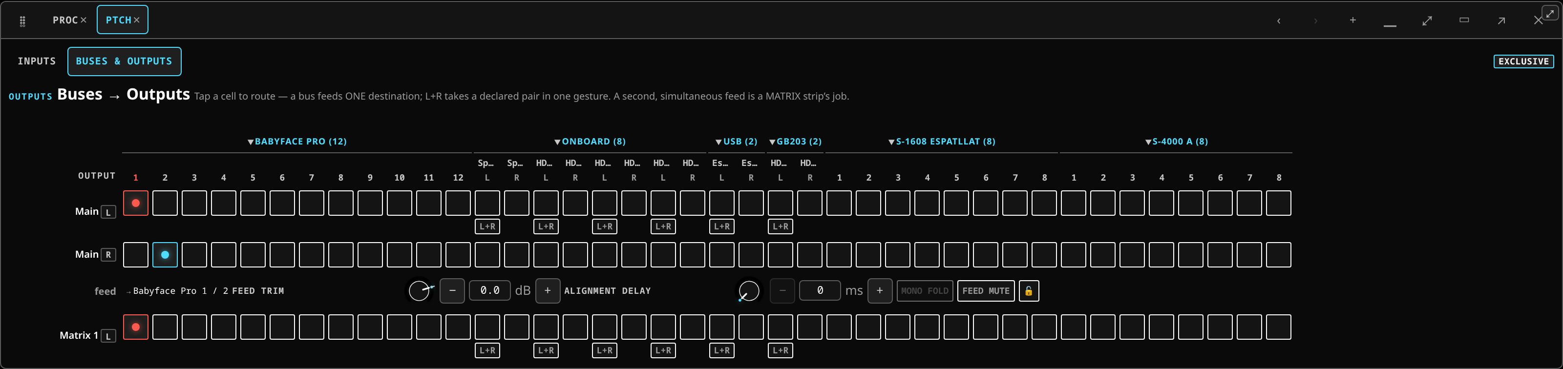 The leg block: every bus and output leg against the physical ports, with the feed trim, alignment delay and mono fold for the selected feed.
A leg is one destination a mix feeds, together with the fixed correction that piece of hardware needs. Other desks call this the output port's own settings: an M32 gives each output a source, a delay and a polarity; a Yamaha CL gives each output port gain, delay and phase; an Allen & Heath dLive gives each socket a delay and a polarity. Same idea, same job.
A leg carries four things. The trim, the fold and the mute belong to the destination as a whole — never to one side of it. The delay is the one exception, and it is per side, because how far away a box is is a fact about that box:
- Feed trim (dB) — this destination leaves the desk hotter or quieter than the others.
- Alignment delay (ms), one encoder per socket — this box is nearer than the one beside it, so its feed is pushed later. Each encoder is captioned by the socket it moves, so the operator dials the box and not a letter. A side that lands on no socket of its own, or that folds onto a socket an earlier side already has, has no box and no encoder.
- Mono fold — a switch: both sides of the mix sum onto this destination's one socket. There is no figure to set. Summing two sides that carry the same thing would arrive twice as loud, so the desk halves each of them, which is the only number that lands the sum back where it started. The switch is available when the destination is one socket; a destination on two sockets has nothing to fold onto, and says so.
- Feed mute — this destination goes silent while the mix keeps running everywhere else.
The controls are drawn on the leg, in one block captioned by where the mix lands ("RME AUX0 / AUX1"). The crosspoint cells above it only say which socket each side lands on; they carry no mute, because a control captioned with one side that silences both is a trap.
The two numbers are encoders, the same control the processing view uses: turn the dial (drag, or the mouse wheel over it), step it with the − and + buttons beside it, or tap the number to type an exact figure. Arrow keys nudge it and Home/End take it to the ends of its travel. The feed trim's dial fills out from 0 dB in both directions, so a cut and a boost are told apart at a glance; the delay fills from one end, because that is all the travel it has. No dial can be turned past the range the desk declares for it. The mono fold has no dial: it is on or off, like the feed mute.
Leg or matrix?
A fixed correction for a piece of hardware is a leg. A feed you operate during the show is a matrix.
A matrix is a bus: it mixes many sources at their own send levels, and it has a fader, a mute, a meter and its own processing. It costs a path from the pool and a strip on the surface. Give a destination a matrix when it needs its own level, EQ or mute during the show. Give it a leg when it needs a number set once and left alone.
A muted feed is visible on the strip
Muting a leg silences that destination only. The mix itself is still running, its fader is up, its MUTE button is off and its meter is healthy — so if the mark lived only in the patchbay, a silent PA would have no visible cause anywhere you were looking.
It does not. The strip that feeds the muted leg wears a FEED MUTED badge naming the destination, and tapping that badge un-mutes it. The same single action is available on the leg block itself. If your mains go quiet and the meters are moving, this badge is the first thing to look for.
Walk-through: patching Main to a device
- Open the patchbay, then the Buses & outputs tab.
- Find the Main rows. A stereo mix has two: Main L and Main R.
- Patch it. Where the device declares a stereo pair, the L+R button beside the L cell puts both sides on it in one gesture. Otherwise click the cell where Main L should land, then the cell for Main R — the two sides are independent, so they may sit on different sockets or even different devices.
- A leg block appears under the two rows, captioned with where the mix now lands. That is the destination, and those are its controls.
- Trim it. Turn the leg's feed trim encoder, or tap its number and type a dB figure. Only this destination changes; the bus fader everybody is mixing on does not move.
- Align it. Set the measured skew in milliseconds on the alignment delay encoder of the socket that box hangs off. A feed can only be pushed later, never advanced, and the box on the other socket keeps whatever it was set to. Two stacks at two distances off one leg is exactly what this is for.
- Mute it. Tap FEED MUTE. That destination goes silent; the mix keeps running. Look at the Main strip on the fader wall — it now carries the FEED MUTED badge naming the destination. Tap either one to bring it back.
- Split L and R. Click Main R's cell on a different socket. The mix's two sides now land in two places; it is still one leg to one destination, with one set of corrections. To join them back onto a declared pair, use the L+R button on the L row.
A mix feeds one destination. If you need a second, simultaneous feed with its own level, that is a matrix — see the crosspoint matrix above.
Worked example: a delay fill under the balcony
Two speakers under the balcony are too far back to hear the mains cleanly. They want the main mix, a little of the vocal aux for intelligibility, at their own level, arriving late enough to line up with the sound coming from the stage.
- Open Patch ▸ Matrix. Rows are the matrix outputs, columns are the buses and mains that can feed them.
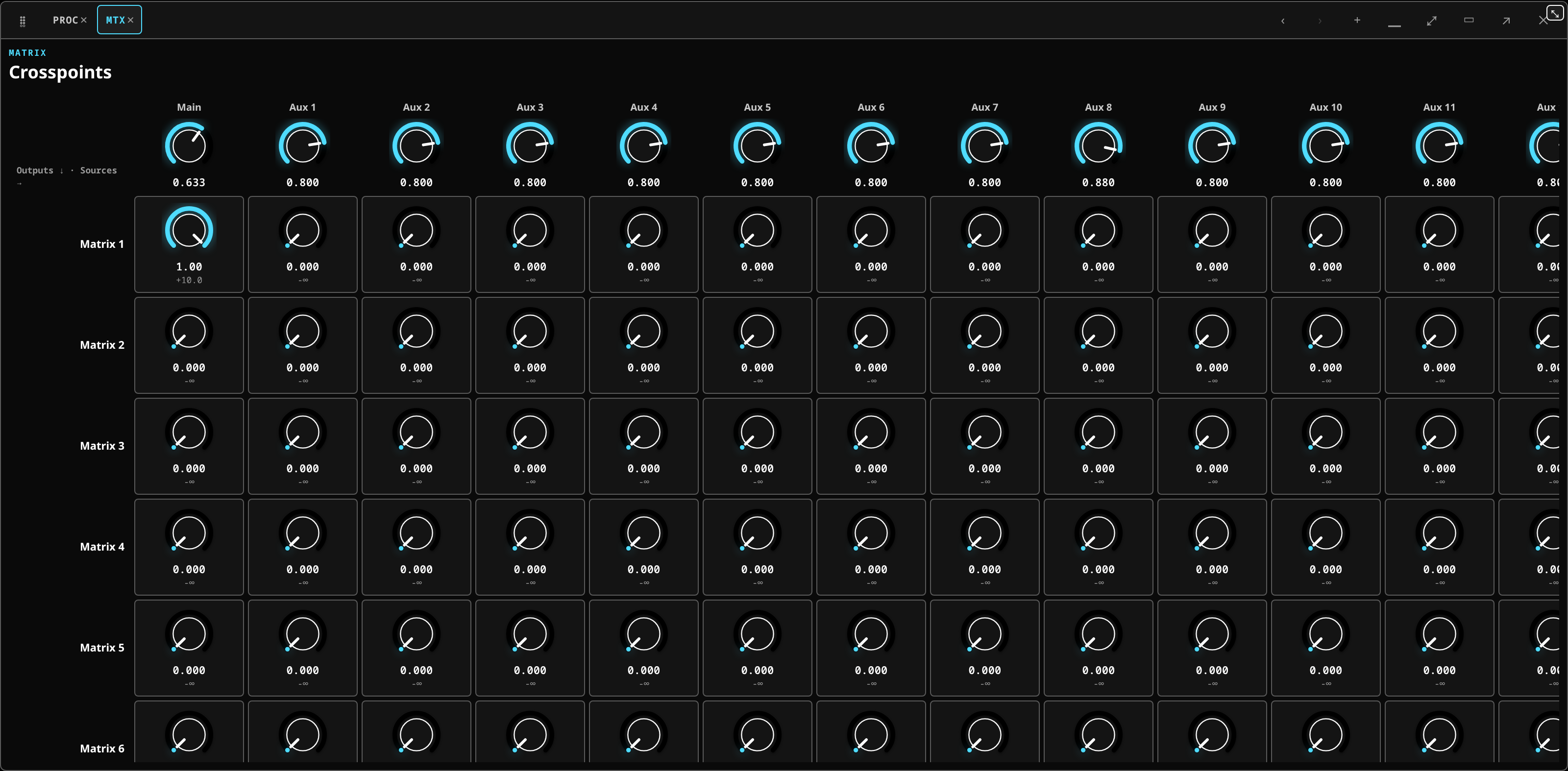 The crosspoint grid with the work zone expanded: a level per cell, and a master per source column.
- Find Matrix 1's row. In the Main column, set the crosspoint to unity, or a few decibels below it. That is the mix the fill carries.
- In the vocal aux's column on the same row, set a level well below the main — a few decibels is usually plenty. The fill is there to make words intelligible, not to be a second PA.
- Set Matrix 1's own fader on the bay's Matrix layer. That is the fill's overall level, and it is the one you will ride if the balcony complains.
- Send it somewhere. Open Patch ▸ Patchbay ▸ Buses & outputs, find Matrix 1's row, and patch it onto the amplifier's socket. A leg block appears under the row, captioned with where it lands.
- Delay it. On that leg, set the alignment delay of the socket the amplifier is on to the time sound takes to travel from the mains to the balcony — roughly 3 ms per metre. Twenty metres is about 58 ms. Turn the encoder, or tap the number and type it.
- Trim it on the same leg if the amplifier wants a hotter or quieter feed than the others.
- Check it. Stand under the balcony. The fill should sound like the stage, only closer, with no slap and no doubled consonants.
What you should see: the matrix output metering when the mains do, the leg block naming the amplifier's socket, and the delay figure standing on the leg.
What it means if you do not:
- The matrix output meters and nothing comes out. The mix is being made and is not reaching hardware. The leg is the place to look — see the main output is silent.
- It comes out but at the wrong balance. You set the crosspoints and forgot the matrix fader, or the other way round. Both are in the path and both multiply.
- It sounds like an echo. The delay is too long. Halve it and work up.
- It arrives early and smears. The delay is too short, or zero. A feed can only ever be pushed later — the desk cannot advance one, because there is nothing to advance it from.
- Changing the vocal in the house changed the fill by more than you meant. That is the matrix doing its job: it is fed from buses, so it follows the mix. If you want a feed that does not follow, feed it from different buses.
Leg or matrix? The delay above belongs to the piece of hardware — it never changes during the show — so it lives on the leg. The level of the fill, which you might ride, is the matrix. That is the whole distinction.
Routing an output to real hardware
The matrix decides what an output carries. Where it physically goes is a routing question, handled in the patchbay: the output routing row picks the real sink each bus, matrix output and the main feeds.
In the patchbay's output grid a stereo bus takes one row per side, and a chip before each row
names the side it carries, such as L or R.
The two are separate on purpose. Re-patching to a different physical output does not disturb the mix you built.
The main output
The Main fader is pinned to the right of the fader bay, outside the paging, and Main has no solo. Its output route is set in the same output routing row as everything else.
If the main meter moves and nothing comes out, that route is where to look: the main output is silent.